- probably the best known technique for higher quality graphics
- The idea behind it is
- To find out what you see when you look in a given direction, consider a ray of light that arrives at your location from that direction, and follow that light ray backwards to see where it came from.
- Or, as it is usually phrased, cast a ray from your location in a given direction, and see what it hits.That's what you see when you look in that direction.
- The operation of determining what is hit by a ray is called ray casting.
- THREE.RayCaster in the three.js API
- take an initial point and a direction (given as a vector), they determine a ray
- The RayCaster can find all the intersections of the ray with a given set of objects in the three.js scene, sorted by distance from ray's starting point.
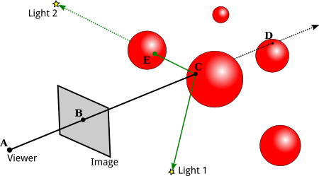
- We are interested in the first intersection, say C
- We need to compute the color of C
- we need a normal vector at C , the material properties of the surface at C , and the light that is illuminating the surface.
- If the angle between one light source (L) and the normal vector is greater than 90 degrees, then the light source lies behind the surface and so does not add any illumination. Otherwise, we can use ray casting again:
- Cast a ray from C in the direction L.
- If that ray hits an object before it gets to the light, then that object will block light from that source from reaching C.
- A ray from a point on a surface in the direction of a light source is called a shadow ray,
- because it can be used to determine whether the surface point lies in the shadow of another object.
- Ray casting is conceptually simple, but implementation details can be tricky.
- surfaces are often given as triangular meshes, with properties specified only at the vertices of the triangles.
- We will have to compute the properties of that intersection point by interpolating the property values at the vertices.
- The interpolation algorithm typically uses something called barycentric coordinates on the triangle:
- If A, B, and C are the vertices of a triangle, and P is a point in the triangle, then
- P can be written uniquely in the form aA + bB + c*C,
- where a, b, and c are numbers in the range zero to one, and a + b + c = 1.
- The coefficients a, b, and c are called the barycentric coordinates of the point P in the triangle.
- How to test whether a line intersects a triangle and how to find barycentric coordinates of the point of intersection?
- There are formulas.
- Basic ray casting can be used to compute OpenGL-style rendering and, with the addition of shadow rays, to implement shadows as well.
- More features can be implemented by casting a few more rays. The improved algorithm is called ray tracing.
- In reality, an object that has a mirror-like surface doesn't just reflect light sources; it also reflects other objects.
- To do that, we can cast a "reflected ray" from A.
- The direction of the reflected ray is determined by the normal vector to the surface at A and by the direction from A to the viewer.
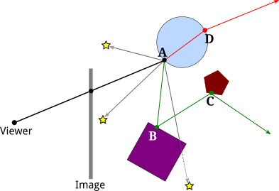
- Here, the reflected ray from point A hits the purple square at point B. and the viewer will see a reflection of point B at A.
- To find out what the reflection of B looks like, we need to know the color of the the ray that arrives at A from B.
- But finding a color for B is the same sort of problem as finding a color for A, and we should solve it in the same way:
- by applying the ray-tracing algorithm to B!
- That is, we use the material properties of the surface at B, we cast shadow rays from B towards light sources to determine how B is illuminated, and—if the purple square has a mirror-like surface—we cast a reflected ray from B to find out what it reflects.
- In the illustration, the reflected ray from B hits a pentagon at point C.
- Because applying the ray-tracing algorithm at one point can involve applying the same algorithm at additional points, ray tracing is a recursive algorithm.
- Ray tracing can be extended in a similar way to handle transparency or, more properly, translucency.
- When computing a color for a point on a translucent object, we need to take into account light that arrives at that point through the object.
- To do that, we can cast yet another ray from that point, this time into the object.
- When a light ray passes from one medium, such as air, into another medium, such as glass, the path of the light ray can bend. called refraction
- The above illustration shows the refracted ray from point A passing through the object and emerging from the object at D.
- To find a color for that ray, we would need to find out what, if anything, it hits, and we would need to apply ray tracing recursively at the point of intersection.
- The ray tracing algorithm is recursive, and, as every programmer knows, recursion needs a base case.
- That is, there has to come a time when, instead of calling itself, the algorithm simply returns a value.
- A base case occurs whenever a casted ray does not intersect any objects.
- Another kind of base case can occur when it is determined that casting more rays cannot contribute any significant amount to the color of the image.
- For example, After reflecting many times, a ray would have very little color left to contribute to the final result.
- A ray can also lose energy because of attenuation of light with distance, and a ray-tracing algorithm might take that into account.
- In addition, a ray tracing algorithm should always be run with a maximum recursion depth, to put an absolute limit on the number of times the algorithm will call itself.
- Although ray tracing can produce very realistic images, there are some things that it can't do.
- For example, while ray tracing works well for point lights and directional lights, it can't handle area lights.
- Another problem with lighting in ray tracing is that it doesn't take into account illumination by reflected light.
- For example, light from a light source should reflect off a mirror, and the reflected light should illuminate other objects.
- OpenGL uses ambient light as an approximation for light that has been reflected and re-reflected many times.
- A better approximation uses ambient occlusion, the idea that ambient light heading towards a surface can be blocked, or "occluded," by nearby objects.
- In path tracing, the idea is to account for all possible paths that the light could have followed.
- In order to model a wide variety of physical phenomena, path tracing uses a generalization of the idea of material property.
- In OpenGL, a material is a combination of ambient, diffuse, specular, and emission colors, plus shininess.
- These properties, except for emission color, model how the surface interacts with light.
- Material properties can vary from point to point on a surface; that's an example of a texture.
- OpenGL material is only a rough approximation of reality. In path tracing, a more general notion is used that is capable of more accurately representing the properties of almost any real physical surface or volume.
- The replacement for materials is call a BSDF, or Bidirectional Scattering Distribution Function. 双向散射分布函数
- Blender's Cycles renderer uses path tracing