- GPU Programming for Video Games
- Notes
- 1. Introduction
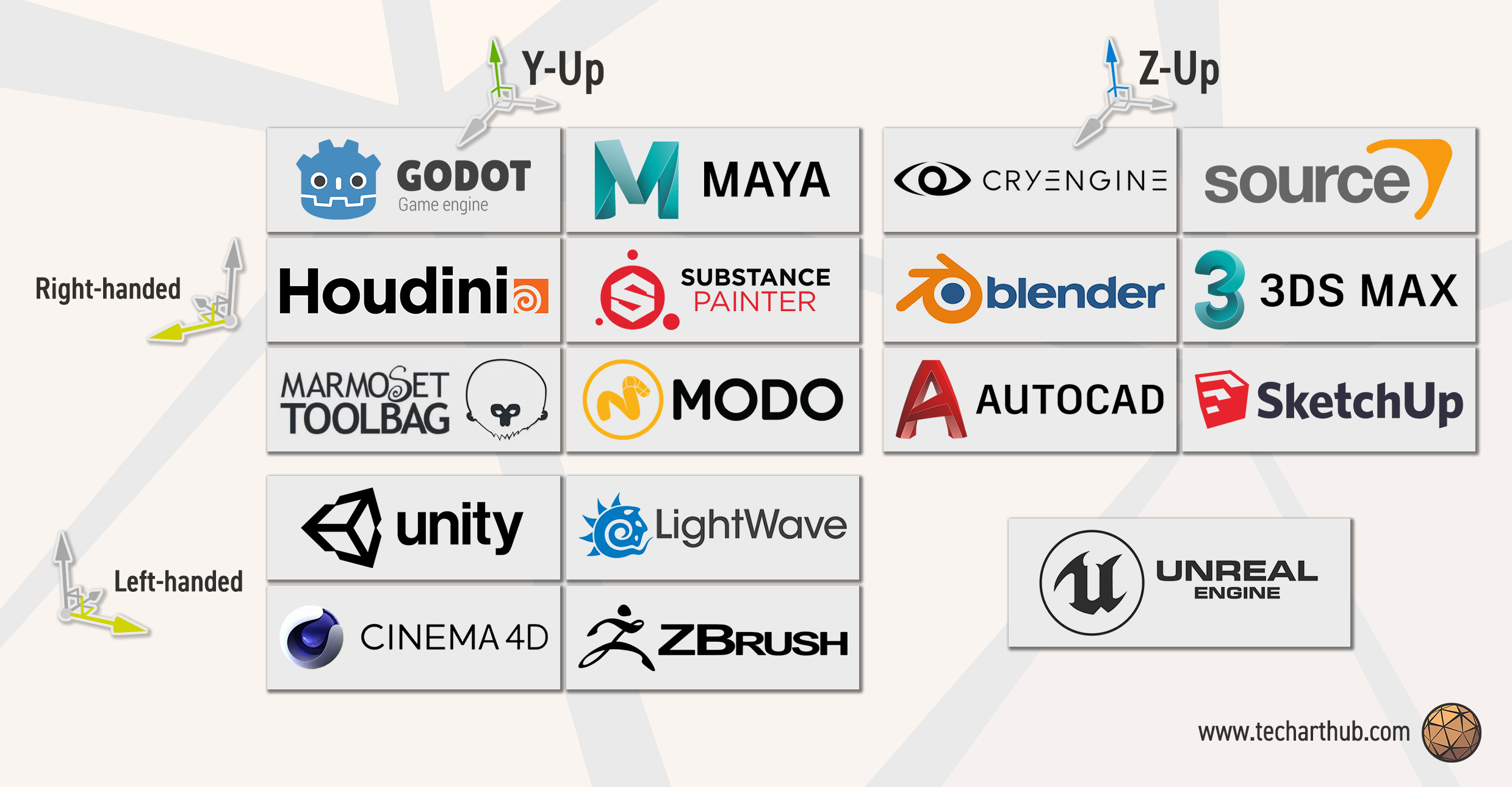
- 2. 3D Coordinate Systems
- 3D Vertex Transformations
- 4 Orthogonal Projection
- 5 Perspective Projection
https://www.youtube.com/watch?v=i5yK56XFbrU&list=PLOunECWxELQQwayE8e3WjKPJsTGKknJ8w
- Unreal(z-up), Unity3D(y-up), and Direct3D use LHS
- but OpenGL and XNA (RHS in eye-space) suddenly turn to LHS in
clip space( canonical view volume )
- but OpenGL and XNA (RHS in eye-space) suddenly turn to LHS in
- moving camera is equivalent to inverse moving the entire world
- rotation must take the coordinate system into consideration.
- LHS , clockwise if looking against axis
- RHS , counter clockwise if looking against axis
- Canonical "clip space" view volume
- D3D/XNA, map z to [0,1]
- OpenGL/Unity, map z to [-1,1]
- World Coordinate System Quick Guide
- CS4455: Video Game Design
- CS4731: Game AI
- CS4496/7496: Computer Animation
- CS4480: Digital Video Special Effects
- The model for creating computer graphics in this class is generally called rasterization model.
- this is in contrast to something like ray tracing.
| Stage | Geometry Pipline | Rasterization Pipeline |
|---|---|---|
| Processing what | Vertices | Pixels |
| Mainly operations | floating-point operations | integer operations |
| Shader | vertex shader(3d vertex) | fragment shader(final color of pixel) |
- Something about the vertex shader is that they process each vertex individually and they don't create new vertices.
- There are other kinds of shader called geometry shaders that can create new vertices
- and there's also computer shaders that are much more general kinds of things that might be thought of as more general-purpose GPU programming.
- We'll be focusing on vertex shader and fragment shader.
-
Math textbooks use z-up

- Z-up, Right-Handed System
-
Real games tend to use y-up
- if we enter the realm of computer graphics

- Right-Handed System, +z toward the viewer
- OpenGL, XNA
-
There are also tools that use left-handed coordinate system ( Y-up )

- Left-Handed System, +z away from the viewer
- Direct3D, Unity3D
-
I shoud note that in traditional 2D games , Y values go downward.
-
There are some tools out there that use a Z-up approach which is closer to math books
- Z-up, Left-Handed System: Unreal
- Z-up, RHS: Quake/Radiant, Source/Hammer, C4 Engine
- Nearly everything still use Y-up for screen coordinates
- even though these kinds of tools use Z-up when it concerns 3D coordinates, when do their final projection onto the 2D screen, they go ahead and use Y for the vertical coordinates.
- if you take the left-handed system here, and rotate 90 degrees (along z axis), you can redraw it, and this is probably what you would see when you pull up the Unreal editor.

- Unreal, Z-up, Left-Handed (rotate)
- Z-up, Left-Handed System: Unreal
-
3D object modeling software
-
- Z-up, Right-Handed System
- 3D Studio Max, Blender
-
- Y-up, Right-Handed System
- Maya, Milkshape


| Summary | Left-Handed | Right-Handed |
|---|---|---|
| Z-up | Unreal | Math textbook, Quake/Radiant, Source/Hammer, C4 Engine, 3D Studio Max, Blender |
| Y-up | Direct3D, Unity3D | OpenGL, XNA, Maya, Milkshape |
- At least at present , the models used in 3D games are formed from triangels.
- each vertex of the triangle also has an associated unit normal, and this arises from the export process that your 3D artist will make from their 3D modeling software.
- Some 3D models may also have color information associated with the different vertices.
- But nowadays vertex colors are not actually used very much.
- because usually that color information is embedded in some sort of 2D texture.
- Sometimes you will see this color slot being used, but it may be used form some other kind of information used in the rendering process and not typical color information.

- Vertex ordering is critical when culling model enabled
- we essentially only want to render the triangles that are faced towards the viewer.
- when approached this is to use the normal vector for the facet.
- PS. these normals for culling are different than the vertex normals used for lighting.
- different vertices have different normals, but only 1 normal for a triangle.
- The way we embed that kind of information is by choosing some sort of order to list the vertices. - in either a left handed system, which in this case, { v1,v3,v2 }
- Question:
- Are you using a LH or RH culling convention for these normal vectors ?
- That could be completely independent about rather your actual 3D coordinate system in your engine is LH or RH.
- Model(World) Transformation
- Model coordinates -> World coordinates
- Model coordinates is what your artist works with. That's the coordinate system they're working within blender, maya, etc...
- We need to transform those coordinates into the world coordinate space and that's basically the view space of the level editor.
- View Transformation
- World coordinates -> Camera space
- Projection Transformation
- Camera space -> View plane
- Model(World) Transformation
- View Transformation

- there are various ways to define a view transformation. but a nice conceptual way is to just imagine that the camera itself is another object in the scene like the box and teapot.
- and if you create the equivalent world transformation matrix that would take a camera, place it at the correct orientation at a certain point in the scene,
- you can then imagine making the view matrix the inverse of that transformation, the inverse of that matrix.
- and if you apply that to all the objects in the scene, it will orbit them around, and rearrange them.
- Projection Transformation
- Set up camera internals
- view frustum
- view planes
- Field of View(FoV)
- There is a rich set of mathematical techniques concerning a concept called
- Set up camera internals
- Enable all transformations to be done by "multiplication".
- primarily for translation
- so we can deal with a series of transformations by pre-multiplying those matrices together before applying them to 10000 vertices.
- Add 4th coordinate (w) to a 3D vecto.
- translation itself can't be accommodated by multiplying a 3x3 matrix.
- Each vertex has [x,y,z,w]
- w will be useful for perspective projection
- where we need to divide by distance, and there is a convention for handling that by sticking the distance into the
w.
- where we need to divide by distance, and there is a convention for handling that by sticking the distance into the
- w should be 1 in Cartesian coordinate system
- w will be useful for perspective projection
- Example of a row-coordinate converion here

- (row-coordinate)

- Direct3D, XNA use row coordinates
- also most documentation for HLSL/Cg uses this row vector convention
- but HLSL itself doesn't really know what convention you're using, it just has these 4D vectors.
- OpenGL, Unity & non-graphics world use column coordinates
- Example of column-coordinate
⎡Xt⎤   ⎡ 1   0   0  Tx⎤  ⎡X⎤
⎢Yt⎥ = ⎢ 0   1   0  Ty⎥· ⎢Y⎥
⎢Zt⎥   ⎢ 0   0   1  Tz⎥  ⎢Z⎥
⎣1 ⎦   ⎣ 0   0   0  1 ⎦  ⎣1⎦

- row-coordinate
[Xs,Ys,Zs,1] =

            ⎡ Sx  0   0  0 ⎤
 [X,Y,Z,1]· ⎢ 0   Sy  0  0 ⎥
            ⎢ 0   0   Sz 0 ⎥
            ⎣ 0   0   0  1 ⎦

-
Rotation is a lot trickier.
- there is lots of different ways to represent rotations.
- some game engine like unity actually use a fairly sophisticated mathematical structure called
quaternions, which are a 4D extension of the complex number to represent rotations. - dealing with quaternions gives a natural way of interpolating camera angles and also dealing with an issue called
gimbal lock. - people design control systems for aircraft, we'll talk about pitch, roll, yaw.
- unity and many other game engines think about a rotation around x-axis , and then rotation around y-axis, and then z-axis. The order you do these things are important.
-
Rotation around x, y,z , in LEFT-Handed System

- clockwise if you're thinking about looking again the particular axis
- counter clockwise if you're thinking about looking down a particular axis
-
If you're in a RHS, the clockwise/counter clockwise should inverse.
- so you may have to check to see what conventions your game engine is using.
-
2D Rotation
[X',Y',1] =

          ⎡ cosθ sinθ 0 ⎤
 [X,Y,1]· ⎢-sinθ cosθ 0 ⎥
          ⎣  0    0   1 ⎦
-
3D Rotation ( LHS )
- for 3D: Rotate along which axis ?
- Rotation along Z axis ( fix z )
[X',Y',Z',1] =

            ⎡ cosθ sinθ 0  0 ⎤
 [X,Y,Z,1]· ⎢-sinθ cosθ 0  0 ⎥
            ⎢  0    0   ⑴  0 ⎥
            ⎣  0    0   0  1 ⎦
- Rotation along Y axis ( fix y )
- be careful about the sign of
sinθ, it's switched
[X',Y',Z',1] =

            ⎡ cosθ  0 -sinθ 0 ⎤
 [X,Y,Z,1]· ⎢  0    ⑴   0   0 ⎥
            ⎢ sinθ  0  cosθ 0 ⎥
            ⎣  0    0   0   1 ⎦
- be careful about the sign of
- Rotation along X axis ( fix x )
[X',Y',Z',1] =

            ⎡ ⑴   0    0   0 ⎤
 [X,Y,Z,1]· ⎢ 0  cosθ sinθ 0 ⎥
            ⎢ 0 -sinθ cosθ 0 ⎥
            ⎣ 0   0    0   1 ⎦

- Most commonly parameterized by
- Position of camera
- Position of point to look at
- Vector indicating "up" direction of camera
- In Direct3D: D3DXMatrixLookAtLH
- D3D use a LHS, but also have D3DXMatrixLookAtRH
- In XNA, Matrix.CreateLookAt (RHS)
- In OpenGL: gluLookAT (RHS)
- In Unity: Matrix4x4.LookAt (LHS)
- but usually a programmer will only call this if they're doing some specialized weird thing because usually there's a camera class with various built-in scripts associated with it that will call such
LookAtroutine for you.
- but usually a programmer will only call this if they're doing some specialized weird thing because usually there's a camera class with various built-in scripts associated with it that will call such
-

-
Projection transform your geometry into a canonical view volumn in normalized device coordinates (clip space)
-
Only X- and Y-coordinates will be mapped onto the screen
-
Z will be almost useless, but used for depth test & advanced postprocessing effects


-

-
Same size in 2D and 3D
-
No sense of distance
-
Parallel lines remain parallel
-
Good for tile-based games where camera is in fixed location (elg. Mahjong or 3D Tetris)

- Canonical view volume ( D3D & XNA )
- Derive x', y'
l ≤ x ≤ r ,   -1 ≤ x' ≤ 1
0 ≤ x-l ≤ r-l
// divided by r-l
0 ≤ (x-l)/(r-l) ≤ 1
// double, and then -1
-1 ≤ 2* (x-l)/(r-l) -1  ≤ 1

-1 ≤ (2x-2l -r+l)/(r-l) ≤ 1
-1 ≤ (2x-l-r)/(r-l) ≤ 1
-1 ≤ 2x/(r-l) - (r+l)/(r-l) ≤ 1

- double multiplier on x/y, and minus a constant
- Derive z' ( slightly different for the range in D3D )
n ≤ z ≤ f ,   0 ≤ z' ≤ 1
0 ≤ z-n ≤ f-n
// divided by f-n
0 ≤ (z-n)/(f-n) ≤ 1
0 ≤ z/(f-n) - n/(f-n) ≤ 1

- a multiplier on z , and minus a constant.
- OpenGL transform for z looks more like x&y transforms.


-

-
In Direct3D: D3DXMatrixOrthoOffCenterLH( *o, l,r, b,t, n,f )
-
In Unity: Matrix4x4.xxx( l,r, b,t, n,f )
-
an interesting thing about the math here, the matrix works regardless of rather you're using a RHS or LHS for your z-axis.
- that is, you can have
f-n, and you could put in number , like n=54, far=104 in a LHS, or n=-50, f=-100 for RHS, you wouldn't have to change any of this - so that leads to something incredibly confusing that took me ages to figure out which is if you look in the Microsoft manual, you'll see that they actually flip
1/(f-n)term for the RHS version of this call( seeOrtho projection matrix (RHS))
- that is, you can have


- Math the same, but z clipping plane inputs in most API calls are negated , so the API need z input parameters be positive
- what's going on ? It turns out even if you're using a RHS , where the near plane in the view space is negative, say -50, these RH API calls expet your near and far plances to be listed as positive numbers.
- so they essentially do that sign flip for you, to prevent people put negative value for n & f.
- In Direct3D: D3DXMatrixOrthoOffCenterRH( *o, l,r, b,t, n,f )
- c based, return matrix to the poiner
*o
- c based, return matrix to the poiner
- In XNA: Matrix.CreateOrthographicOffCenter( l,r, b,t, n,f )
- In OpenGL, glOrtho( l,r, b,t, n,f) (matrix is different, also use positve n & f)
- OpenGL maps z to [-1,1] & uses column vectors
- c based. GL has a strange stack based computational model. a lot of their operations will create a matrix and shove onto the stack that then gets popped off later.

-
In most orthographic projection setups
- Z-axis passes through the center of your view volume
- Field of view (FOV ) extens equally far
- r = -l
- t = -b
-

- we do need to keep the flexibility of have different near and far planes.
-
In Direct3D: D3DXMatrixOrthoLH( *o, w,h, n,f )


- In Direct3D: D3DXMatrixOrthoRH( *o, w,h, n,f )
- In XNA: Matrix.CreateOrthographic( w,h, n,f )

-

- we're going to do is take this frustum , and project it into a rectangular volume.
-
choosing the near and far plane is important from a practical issue in both orthographic and perspective projection because the z inforamtion is used to determine which objects are closer thant other objects in particular which objects are obscuring other objects.
- if set your near and far plane too far apart, you may not have enough resolution in z to resolve that wel, and you can get the strange shimmering effect called Z fighting.
-

-
Given a point (x,y,z) within the view frustum, project it onto the near plane z=n , x∈[l,r], y∈[b,t]
-
We will map x from [l,r] to [-1,1], and y from [b,t] to [-1,1]


- To calculate new coordinates of x" and y"
$$x"/x = n/z ⇒ x" = nx/z y"/x" = y/x ⇒ y" = ny/z$$ - this transformation is non-linear. we're going to have to do a division operation that you can't do with just a straight matrix multiplication.
- The next step is to map these x", y" into a [-1,1] clip space.

- the
zin the first equation is not something we can represent with a matrix. - but if we multiply everything through by z, and just say, ok well we're not going to be dealing with x',y'.
- What we're going to have here is
x'·zandy'·z. - We're just going to say everything's going have z in it, and we'll get rid of that z later.
- What we're going to have here is
- and I can express this as a matrix computation.
- We'll need to think a bit about what we want to do with z'.
- We know z(depth) transformation has nothing to do with x, and y.
- Let's keep things consistent.
$$z"·z = p·z + q , where p and q are constants.$$ - and try to figour out something here that make sense.
- we know, (D3D) z'=0 when z=n, z'=1 when z=f , ( OpenGL z'=-1 when z-n )
$$0·n = 0 = p·n + q 1·f = f = p·f + q$$ - solve these equations
- Combine those equations
$$x'·z = ... y'·z = ... z'·z = ... w'·z = z$$ 
- now I've got a question of what do I really want to do with this
w'?- the convention is that in any case we will have to divide by z to obtain
[x',y',z',w'] - implemented by dividing by the fourth (w'z) coordinate
- the convention is that in any case we will have to divide by z to obtain


-
if l=-r, t=-b (D3D)
-
but even then expressing things terms
w,his usually how these kind of matrices are expressed.- usually there's a field of view (FOV) expressed in either radians or degrees, in order to find the width, defined in vertical direction.
- and then a aspect radio defined in order to find the width.
- aspect radio = Width/Height

-

$$tan(ɑ/2) = (h/2)/n = h/(2n) ⇒ 2n/h = 1/tan(ɑ/2) r = w/h ⇒ 2n/(w/r) = 1/tan(ɑ/2) 2n·r/w = 1/tan(ɑ/2) 2n/w = 1/r · 1/tan(ɑ/2)$$ -
LHS

- In Direct3D: D3DXMatrixPerspectiveFovLH(*p, a,r,n,f)
- In Unity:Matrix4x4.Perspective(a,r,n,f)
-
RHS

- In Direct3D: D3DXMatrixPerspectiveFovRH(*p, a,r,n,f)
- In XNA:Matrix.CreatePerspectiveFieldOfView( a,r,n,f )
- In OpenGL: gluPerspective(a,r,n,f)


- https://docs.unity3d.com/ScriptReference/Camera-projectionMatrix.html
- From Camera.projectionMatrix documentation:
If you change this matrix, the camera no longer updates its rendering based on its fieldOfView. This lasts until you call ResetProjectionMatrix. Use a custom projection only if you really need a non-standard projection. This property is used by Unity's water rendering to setup an oblique projection matrix. Using custom projections requires good knowledge of transformation and projection matrices.
- The actuall 2D projection to the viewer
- Copy to your back buffer (frame buffer)
- Can be programmed, scaled, ...
- Viewport space
- (0,0) is bottom-left
- (1,1) is top-right
- Screen space coordinates
- z "is in world units from the camera"
- (0,0) is bottom-left
- (Camera.pixelWidth, Camera.pixelHeight) is top-right
- GUI space coordinates
- (0,0) is upper-left
- (Camera.pixelWidth, Camera.pixelHeight) is bottom-right