HIGH VOLTAGE electricity involved! Use at your own risk. Work under proper supervision if you are a minor. I take no responsibility for any accidents that may occur from using this code.
- Modern responsive web interface
- Asynchronous webserver for better performance
- Real-time page updates using JavaScript XMLHttpRequest
- ESP-NOW time broadcasting to other ESP devices
- Multiple control modes:
- Automatic (time-based)
- Power Saver
- Timer
- Manual
- Intuitive status display on web interface
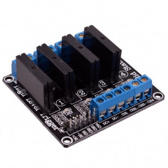
- Solid State Relay support for reliability
- Over-the-Air (OTA) updates
- Automatic time synchronization
- Visual feedback and WiFi signal indicators
- DS3231 - RTC module
- NTPClient - Network time
- Other libraries available via Arduino IDE Library Manager:
- ESP8266WiFi
- ESPAsyncTCP
- ESPAsyncWebServer
- Adafruit_GFX
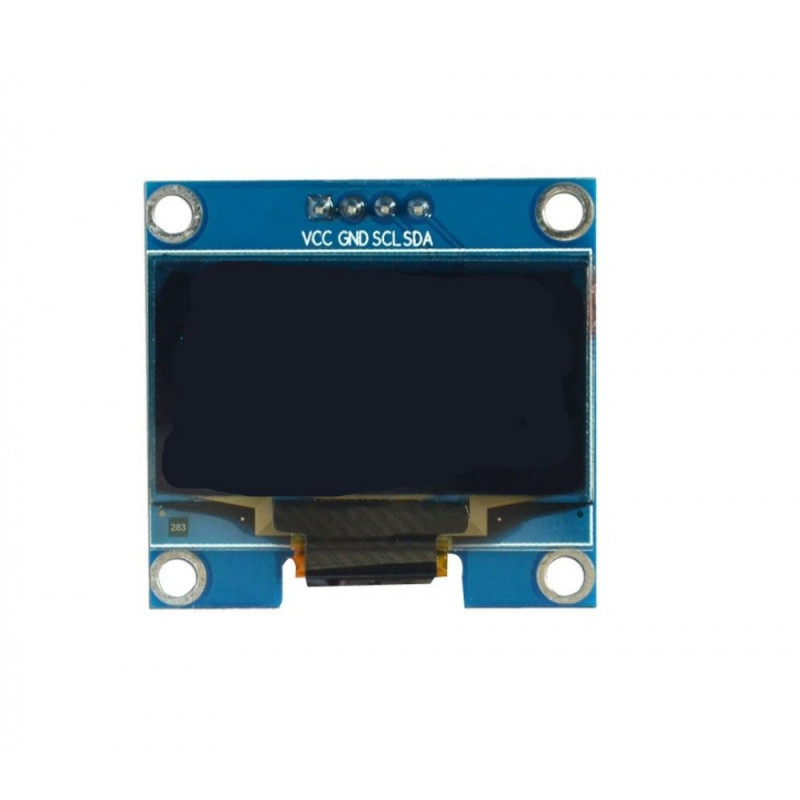
- Adafruit_SSD1306
Add this URL in Arduino IDE:
http://arduino.esp8266.com/stable/package_esp8266com_index.json
File → Preferences → Additional Boards Manager URLs
| NodeMCU | Device |
|---|---|
| D1 | SCL |
| D2 | SDA |
| 3.3V | VCC |
| GND | GND |
Note: Both I2C devices share the same pins. For I2C address conflicts, adjust pull-up resistor values.
| NodeMCU | Relay |
|---|---|
| D3 | IN1 |
| D5 | IN2 |
| D6 | IN3 |
| D7 | IN4 |
Important: Use separate power supply for relay board. Connect GND between NodeMCU and power supply.
-
Relay Board
-
RTC Module
-
Microcontroller
-
Display
- Appropriate power supplies
- Electrical switches (recommended in series with relays)
- Connecting wires
- Project enclosure
See Issues for planned features and improvements.
If you've made improvements to the code, please share them! Contact me with your updates.


